Integrate Sungrow with Reduxi controller via Modbus TCP/IP using a Dongle, Logger, or CL300 for maximal flexibility, cost, and energy reductions.

1. Sungrow Documentation
User manual Dongle WiNet S/S2:
User manual Data Logger 1000:
User manual Data Logger 4000 (See Chapter 2.2):
User manual LC300:
2. Supported Sungrow Devices
| Type | Models | Connection type |
| Sungrow String Inverter 3p | SGXXX-XX Series |
WiNet- S/S2 (Chapter 2.1) Data Logger (Chapter 2.2) |
| Sungrow Hybrid Inverter 3p | SH Series |
WiNet- S/S2 (Chapter 2.1) Data Logger (Chapter 2.2) |
| ESS C&I | STXXX kWh series / Power stack | Sungrow CL300 Local Controller (Chapter 3) |
2. How to connect Sungrow String/Hybrid Inverter
2.1 Connection Through WiNet-S/S2 Dongle
The Connection through the WiNet- S/S2 Dongle allows for Wifi or LAN connection to the local network.
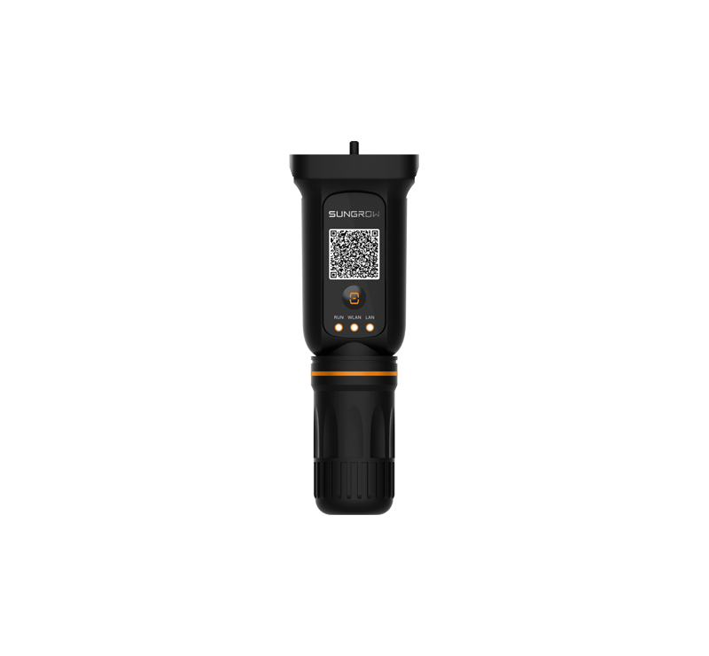
2.1.1 Physical Installation of WiNet-S/S2 to Inverter
This example follows the generic installation manual of the WiNet to Sungrow Inverter. For more detailed information, check the Sungrow documentation in chapter 1 of this manual.
2.1.2 Open Modbus TCP on WiNet Dongle
For the Reduxi to be able to communicate with the Sungrow inverter, Modbus TCP must be enabled on port 502. This can be done directly on site by connecting to the WiNet Web Ui or via the iSolar Cloud Web App on your computer.
2.1.3 Open Modbus Locally
Connect to the WiNet-S/S2 Web Ui
Go To: System - forwarding Configuration and enable port 502
To find the Modbus unit ID for the Inverter
Go to: Device - Device List and check the Forwarding Modbus ID of the inverter
The same Modbus ID must be provided in the Reduxi Configurator.
2.1.4 Open Modbus on iSolar Cloud Web App
Log in to the iSolar Web App on your computer.
Go to: Settings - Device parameters - Common Settings of the WiNet Dongle
In the common settings of the WiNet Dongle
Go to: Modbus TCP 502 Port on/off and select open
2.2 Connection of Inverter with Reduxi Through Data Logger 1000/4000
For more detailed instructions, see the documentation on Sungrow for Data Logger 1000 and Data Logger 4000
2.2.1 Establish a Physical connection between the Data Logger and the Inverters with an Ethernet cable (RJ45).
2.2.2 Establish a physical LAN connection with Reduxi
Connect the Data Logger 1000/4000 through Ethernet to the Reduxi Controller.
3. Connection of ESS C&I (ST battery Series) Through Sungrow LC300
3.1 Physical LAN Connection of the LC300 with the Battery and Reduxi
Connect the LC300 on the ST battery directly to Reduxi through Ethernet. The Positions of the Ethernet communication ports are shown in the figure below.
Log in to the LC300 web UI and
Go to: Parameter Settings - Comm Parameters and make sure the IP address, Subnet mask, and Gateway are set according to the local network for Ethernet.
The Modbus port is set to 502 and is open by default, as seen in the picture below. Save configured settings.
Now you can go to System Parameters and set the Local/remote settings to Local/Remote. Also, ensure that you change the time setting to 'Web Time Synchronization' and set the time manually.
4. Add Sungrow in Reduxi Configurator
4.1 Add Sungrow String Inverter
First, log in to the local Reduxi configurator and add a new device by clicking the 'Add device' button.
4.1.1 Select Sungrow String Inverter
Within the first step, basic settings are defined:
- Select Device type: Solar Power Plant / Hybrid, depending on the system
- Select Type: Sungrow string/hybrid inverter 3p
- Name the device accordingly
4.1.2 Device Configuration for Communication Channel
The second step involves configuring the communication channel. In this step, the communication link between the Reduxi controller and the Sungrow String Inverter is established.
- Connection: Choose TCP
- IP: Enter the IP address of the Inverter
- Modbus ID: Enter the Modbus ID previously obtained from the WiNet S/S2, Data logger, or CL300 web interface
4.2 Add Sungrow ESS C&I (ST Battery Series)
Add a new device by clicking the 'Add device' button.
4.2.1 Select Sungrow ST Battery
Within the first step, basic settings are defined:
- Select Device type: Battery
- Select Type: Sungrow ST
- Name the device accordingly
4.2.2 Device Configuration for Communication Channel
The second step involves configuring the communication channel. In this step, the communication link between the Reduxi controller and the Sungrow String Inverter is established.
- Connection: Choose TCP/IP
- IP: Enter the IP address of the Inverter or use the button "Scan for IP" to find the IP adress of the LC300
-
Modbus ID: Enter the Modbus ID previously obtained from the LC300 web interface
4.3 Test Communication
Below all fields of the Communication channel mentioned in the previous step, there is a "Test Communication" button. This button is used to verify whether the Modbus connection between the devices is functioning correctly.
Successful response:
Unsuccessful response:
5. Last measurements
After successfully establishing communication with the newly added device, its values can be checked under Devices- Sungrow - Last Measurements in the Reduxi configurator as an additional test.
For advanced battery control, integrate the device into the strategy of the Reduxi system. Under Devices/Sungrow in the Reduxi configurator, the control type must be set to AUTO so commands for the strategy will affect the Inverter.
To achieve maximal flexibility and energy cost reduction with respect to dynamic price and dynamic tariffs, please follow the instructions on how to define a strategy at this link: Strategies for Reduxi controller.
After successfully adding the device, it can also be monitored and controlled via the Reduxi application.