Connect Nibe Heat Pumps to Reduxi Gateway Through SG-ready contacts and Save up to 30% on energy costs by enabling dynamic control to align with fluctuating energy prices.
1. Nibe Documentation
Nibe S-Series:
2. Required components for connecting the Reduxi controller to the Nibe heat pump.
To establish the connection between the Reduxi controller and the Nibe heat pump, two components are needed:
- Reduxi Controller
- Reduxi Gateway device with 3x (30:1A) current sensors (CTs)
The Reduxi Gateway device must be first added (connected) to the Reduxi controller to control/commission the heat pump operation modes. The connection can be established wirelessly (WLAN) or wirely via a UTP cable (LAN). You can find more about the connection at the Gateway to Controller connection. The Reduxi Gateway device also includes 3x(30:1A) current sensors (transformer) used to measure the electrical current (i.e. power) for each phase of the heat pump. Additionally, two relay outputs are used for generating signals to SG-ready contacts, affecting the heat pump operation modes.
3. Connection Scheme of the Reduxi Devices and Nibe
3. Physical Connection of Reduxi Gateway to Nibe
The physical connection between the Reduxi Gateway and Nibe are done in two steps
- Connection of the Reduxi Gateways relays to Nibe SG Ready Contacts
- Connection of the Reduxi Gateways Current Sensors (CT) to the Power Phases L1, L2, L3
3.1 Connection of Reduxi Gateway relays to Nibe SG-Ready Contacts
To physically connect the relays of the Reduxi Gateway device to the SG-ready contacts on the heat pump, it is essential to determine the exact locations of the SG-ready contacts on the heat pump’s circuit board.
Please make sure to adhere to the user manual of your specific Nibe Device to find the SG-Ready contacts.
The figure below illustrates how the physical connection should be made between the SG-Contacts and the Reduxi Gateway.
The Connection should be done in the following way:
Connection of Relay 1 to Smart Grid Ready 1:
- Connect the NO contact of the Reduxi Gateway relay 1 to the DIG 1 contact on HP
- Connect the COM contact of the Reduxi Gateway relay 1 to the COM contact corresponding to relay 1 on the HP
Connection of Relay 2 to Smart Grid Ready 2:
- Connect the NO contact of the Reduxi Gateway relay 2 to the DIG 2 contact on HP
- Connect the COM contact of the Reduxi Gateway relay 2 to the COM contact corresponding to relay 2 on the HP
3.2 Connection of the Reduxi Gateway's Current Sensors
The current sensors (CTs) are included in the Reduxi Gateway kit.
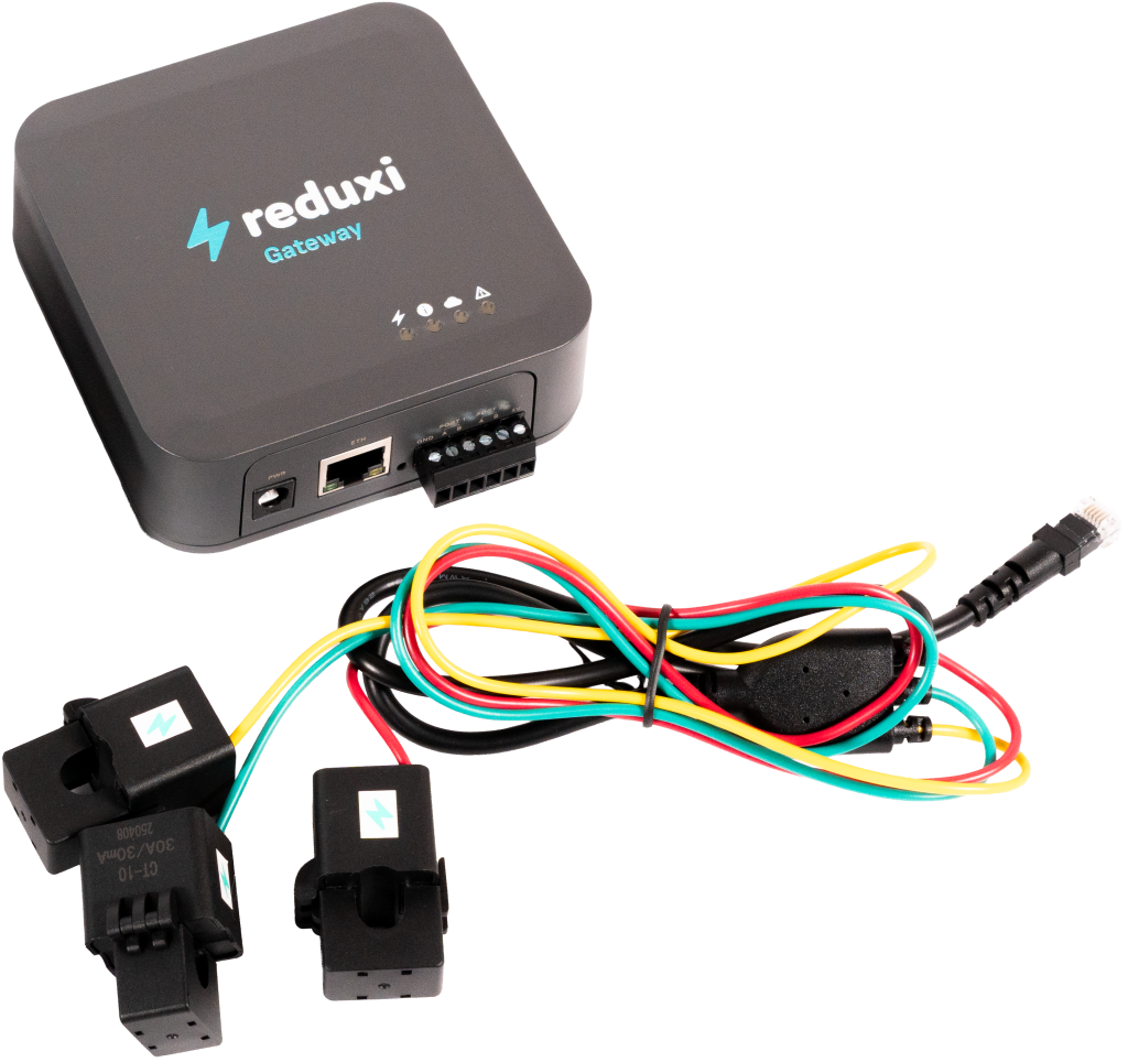
The current sensor covers the heat pump's individual phase wires (L1, L2, L3), see picture below.
Important note: The CTs of the newer Reduxi Gateways are color-coded and have the following convention
- Red: L1
- Green: L2
- Yellow: L3
4. Add Nibe Device in the Reduxi Configurator
4.1 Add Device
First, log in to the local Reduxi Configurator and add a new device by clicking the 'Add device' button.
4.2 Select
Within the first step, basic settings are defined:
- Select Device type: HVAC
- Select Type: Reduxi Meter
- Name the device according to the model
4.3 Configure the Communication Settings
The Communication settings consist of three parts:
- Communication channel
- Current Sensor Settings (CTs)
- Definition of Relay signals in relation to SG ready Contacts
In the first step, we define the connection type TCP/IP, IP address of the Reduxi gateway, Modbus Port, and Modbus Unit ID. These settings are predefined and can be left as they are. If you have trouble connecting, try scanning for the Reduxi Gateway's IP address by clicking "Scan for IP."
In the second step, we can define the current sensor settings of the Reduxi Gateway. Choose Autodetect from Gateway as seen below.
In the third step, the signals from the relays of the Redux gateway device are defined. The following table illustrates the operation modes of the heat pump:
| Reduxi Operating Mode | Nibe Operating mode | SG-Ready iutput contact | Setting |
| OFF Mode | Forced OFF Mode |
Smart Grid Ready 1 Smart Grid Ready 2 |
on (closed) off (open) |
| ECO Mode | Normal Operation |
Smart Grid Ready 1 Smart Grid Ready 2 |
off (open) off (open) |
| ON mode | Enhanced Comfort |
Smart Grid Ready 1 Smart Grid Ready 2 |
off (open) on (closed) |
| Boost mode | Forced on |
Smart Grid Ready 1 Smart Grid Ready 2 |
on (closed) on (closed) |
The Configuration on the Reduxi communication channel should then be done as follows.
For the Forced OFF mode
For the normal operation mode (ECO mode on reduxi)
For the Enhanced Comfort Mode (ON mode on reduxi)
For the Forced ON mode (Boost mode on reduxi)
5. Test Communication
The next step is to test the communication.
The communication test is carried out with the help of the "Test communication" button, located on the lower right side after all the parameters fields of the communication channel.
The communication test can return two answers:
1. Communication is working properly, picture below:
2. Communication is not working properly, the picture below:
6. Last measurements
After successfully establishing communication with the newly added device, its values can be checked under Devices/Nibe heat pump in the Reduxi configurator as an additional test.
For advanced heat pump control, integrate the device into the Reduxi system strategy. Under Devices/Nibe in the Reduxi configurator, the control type must be set to AUTO so commands for the strategy will affect the heat pump.
To achieve maximal flexibility and energy cost reduction with respect to dynamic price and dynamic tariffs, please follow the instructions on how to define a strategy at this link: Strategies for Reduxi controller.
After successfully adding the device and checking the values, the device can also be inspected and controlled via the Reduxi application.