Integrate CHINT C&I ESS with Reduxi controller via Modbus TCP/IP for maximal flexibility, cost, and energy reductions.
![]()
1. Chint Power Documentation
CPS ES-125kW-261kWh-EU:
2. How to connect Chint Power ESS
2.1 Physical connection
The CHINT Energy Storage System (ESS) supports the Modbus TCP protocol for communication with the Reduxi controller. It must be connected via an Ethernet cable (Cat5 or Cat6) to the same local network as the Reduxi controller, or directly to the Reduxi device. The connection is made through the LAN1 network port on the LEMS module of the ESS.
2.2 Activate communication
2.2.1 Modbus TCP
The ESS system supports Modbus TCP communication for third‑party EMS/Reduxi. Communication is performed via the LAN1 port of the LEMSmodule. In most installations, no dedicated “enable Modbus” action is required. After commissioning, ensure that:
- the LEMS has a valid IP address on the local network,
- Reduxi can reach the device over the network, and
- TCP port 502 is opened on the ESS
If communication does not work, check the ESMU network settings in the local interface and consult CHINT documentation/support.
2.2.2 EMS settings (System Remote Dispatch Mode)
In order for Reduxi to control the Chint ESS, the settings in the web interface must be adjusted.
The BMS is located on the inside of the door. If you are prompted for a password upon activation by touch, the following data must be entered by default:
Username: admin
Password: 12345678
Afterward, you will be taken to the system's main page.
-
Go to the "Settings" submenu:
-
Select "Dispatch mode":
-
activate "System remote Dispatch"
3. Add Chint Power ESS in Reduxi Configurator
After connecting the Reduxi and the ESS device, you can register it as a new device (CHINT CPS ES-125kW-261kWh-EU).
3.1 Add device
First, log-in to the local Reduxi configurator and add a new device by clicking the 'Add device' button.
3.2 Select CHINT CPS ES-125kW-261kWh-EU
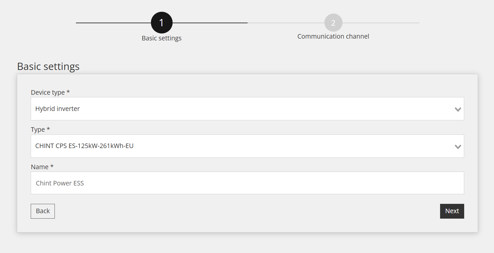
Within the first step, basic settings are defined:
- Select Device type: Hybrid Inverter,
- Select Type: CHINT CPS ES-125kW-261kWh-EU,
- Name the device as you wish, as an example: Chint Power ESS
3.3 Device Configuration for Communication Channel
The third step involves configuring the communication channel, which is essential for proper Modbus TCP/IP communication. In this step, the communication link between the Reduxi controller and the Chint Power ESS device is established.
Settings for the Communication channel are displayed below:
- Connection: TCP/IP
- IP: Enter the IP address of the Chint Power ESS (you can scan the network to find desired IP address)
- Port: 502
- Modbus unit ID: This is the same ID as set on the inverter (as default 1)
- Control mode: Choose which EMS modes should be used to control the EMS.
- Are electricity meter and PV connected: Set yes if the electricity meter and PV are connected directly to the ESS device.
3.4 Test communication
Below all fields of the Communication channel mentioned in the previous step, there is a "Test Communication" button. This button is used to verify whether the Modbus TCP/IP connection between the devices is functioning correctly.
Successful response (example):
Unsuccessful response (example):
In this case, check the network cabling, the IP settings, and the settings on the Reduxi controller, and try again.
3.5 Readings from Device
This section shows you how to check the device's measured values and whether it is communicating correctly. This can be done under "Devices /Chint Power ESS /Last Measurement."
For advanced control, integrate the device into the Optimization modes of the Reduxi system. Under Devices /Chint Power ESS in the Reduxi configurator, the control type must be set to AUTO so that commands for strategy will affect the battery.
To achieve maximal flexibility and energy cost reduction with respect to dynamic price and dynamic tariffs, please follow the instructions on how to define strategy at this link: Strategies for Reduxi controller.
After successfully adding the device, it can be monitored and controlled via the Reduxi application.